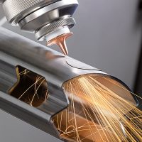
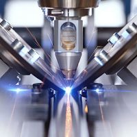
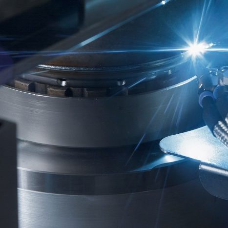
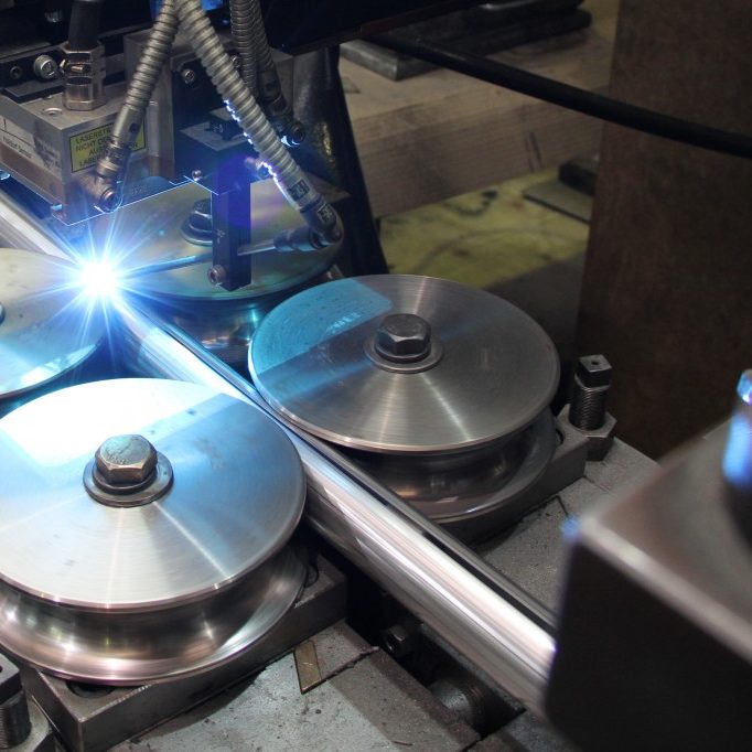
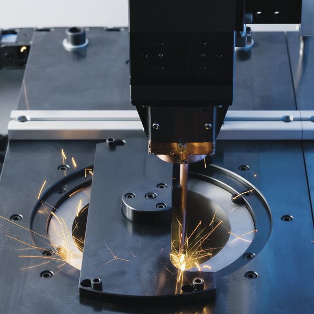
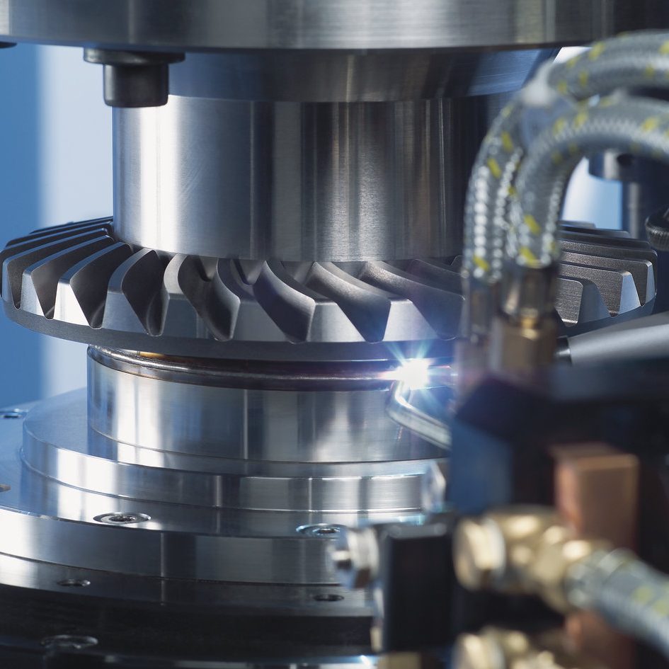
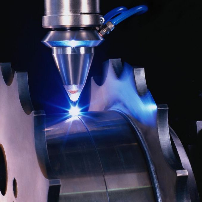
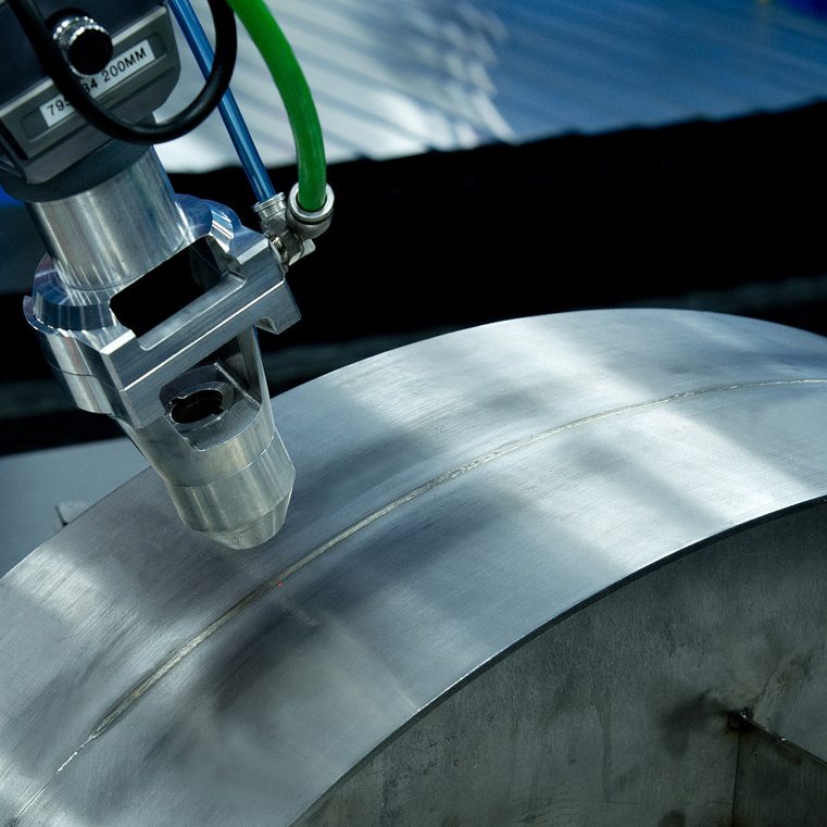
Laser welding, a non-contact joining procedure.
The laser beam offers different possibilities for joining metals. You can join parts by their surface or generate deep weld seams. It can be combined with conventional welding procedures and, moreover, it can also weld with filler material.
There is no tool that can be used in such a diverse way as the laser. With it, fine weld spots with a diameter of 1 mm can be created very quickly, as well as deep weld seams of several meters long. With minimal deformation, very fine seam geometries with a large depth-to-width ratio can be created. Lasers weld materials with a high melting temperature, as well as others with high thermal conductivity. Thanks to their reduced fusing, and easily controllable short fusing time, they can even join materials that otherwise cannot be welded or can only be welded with difficulty. If necessary, additional materials are used.
Laser welding allows to perform the joining using individual laser pulses or in a continuous way. The geometry of the seam describes how the edges of the parts to be joined match with each other. Different types of welding (spot or continuous) require different modes of operation in the laser source.
Pulse operation
This mode emits a laser beam interrupted in time. The important parameters for material processing are the pulse duration, pulse energy and frequency.
Continuous mode
This mode of operation is based in the excitation of the active medium in a continuous way to generate an uninterrupted laser beam.
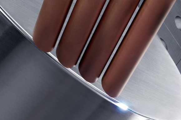
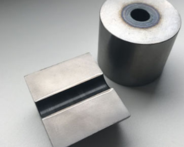
When the steam comes out, it exerts pressure on the casting and causes displacement of a part of it. The piece continues to melt away. This is followed by a deep, narrow, steam-filled hole: it is named the steam capillary, also called keyhole. The keyhole is surrounded by molten metal. When the laser beam moves through the joint, the vapor capillary also moves through the part. The molten metal flows around the steam capillary and solidifies at the back. In this way, a narrow and deep welding seam with a homogeneous structure is formed. The seam depth can be up to 10 times greater than the seam width and can achieve up to 25mm. The laser beam is reflected multiple times on the melted walls of the keyhole. By doing so, the casting absorbs almost completely the laser beam and the efficiency of the welding process is increased. When we weld with lasers, the steam of the keyhole also absorbs the laser light and it is partially ionized. The consequence is the appearance of plasma. The plasma also provides energy to the part. Thus, penetration welding is characterized by a high level of performance and high welding speeds. The high speed causes that the zone of thermal influence is reduced, and then, the deformation is slight. This procedure is used when high weld depths are required or when multiple layers of material need to be welded at one time.
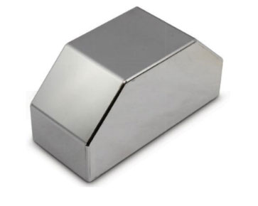
During thermal conduction welding, the laser beam melts the parts to be joined along the joint. The flow of the castings converges to end up solidifying in a weld seam. Thermal conduction welding is used to join thin-walled parts, for example corner seams at the visible edges of housings. Other applications are also seen in electronics. The laser generates a smooth and rounded weld seam that does not require further machining. In the applications mentioned, both pulsed or continuous solid state lasers are valid. With thermal conduction welding, energy only penetrates the part through thermal conduction. For this reason, the seam depth can only be between a few tenths of a millimeter to 1 mm. The thermal conductivity of the material limits the maximum seam depth. The seam width is always greater than the seam depth. If the heat cannot flow quickly enough, the processing temperature rises above the evaporation temperature. The consequences are the formation of metallic vapor, a sudden increment in the depth of weld and that the process be turned into a penetration welding.
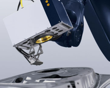
In scanner welding, the beam is guided by movable mirrors (galvanometers). The beam is guided by the angular movement of the mirrors. This results in a field of processing in which welding can be performed precisely and highly dynamically. The size of the field depends on the working distance and the deflection angle. The processing speed and the size of the focus diameter in the part depend on the reproduction properties of the optical system, as well as the angle of incidence of the beam, the quality of the laser beam and the material. The movement of an additional lens system allows that the focal point can also be moved with extraordinary dynamism in the Z direction, thus allowing the 3D components to be processed without moving the processing head or the component. The travel movements are so fast that downtime is practically eliminated completely and the laser device can be producing for almost 100% of the available production time.
While welding is performed, the scanner optics can also be guided through a workpiece in combination with a robot. This “flying” movement is what ended up defining the term “welding on the fly” (also called remote welding). In this case, the robot and the optical scanner system synchronize their movements in real time. The use of a robot expands the work area significantly and offers the possibility of real three-dimensional processing of the part. When a galvo head is programmed you can use a very convenient editor that allows you to build welding figures for a part and save them. The laser source used is a high-power fiber laser with excellent beam quality. One or more flexible fiber optic cables guide the laser light from the laser device to the point of work.
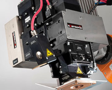
LASERLOGY, offers its customers laser welding robots and machines with the latest technologies in the industry. In an industrial sector characterized by business concentration and the standardization of products and services, the offer of flexible solutions and personalized customer service are two fundamental assets for the development of the companies . At LASERLOGY, we are passionate about providing a close professional treatment, based on strict quality standards. We are constantly evolving and we adapt every day to market demand, providing tailor-made solutions for a customer that know he want. In short, we are walking in the same direction to grow together, innovating, attending to market trends and the needs of each company, and demanding ourselves more every day, to optimize the solutions that we provide to each client.


